亚洲自偷自偷在线成人网址-中国凸偷窥xxxx自由视频妇科-2021国内精品久久久久精免费-日本少妇被黑人xxxxx-精品偷拍被偷拍在线观看

+ 86 - 20 - 3992 0957
English
HomeSplice crimping
SPLICE CONNECTION - FROM WIRES AND PCB TO DIODES AND COILS
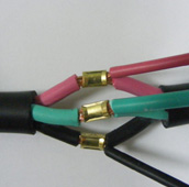
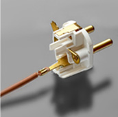
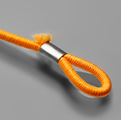
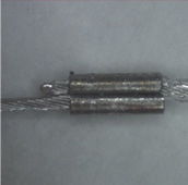
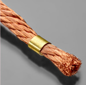
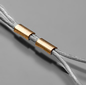
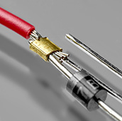
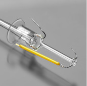
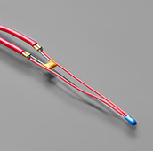
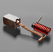
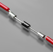
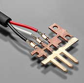
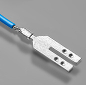
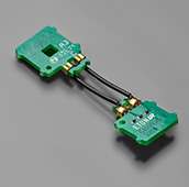
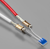
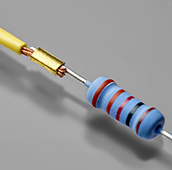
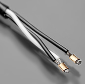
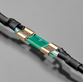
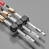
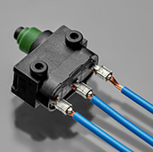
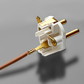
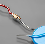
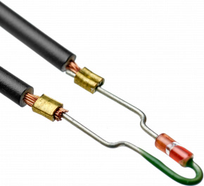
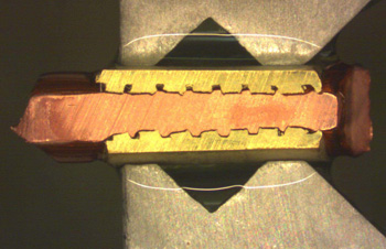
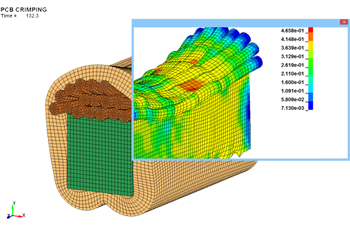
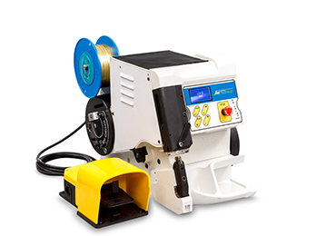
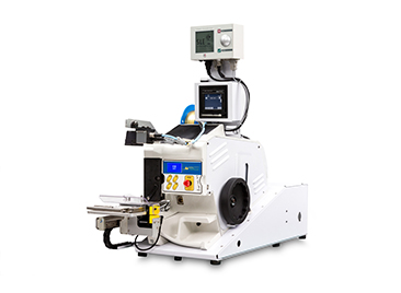
Splice is a solderless crimp connection formed by crimping a metal clip onto the ends of the components.

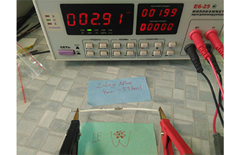
Unlike standard terminals, splice connection is applicable to any electrical components of various dimensions and materials: wire, PCB, coil, capacitor, sensor, diode, lead frame, textile, etc. In contrast to welding and soldering, it is vibration resistant and its quality can be evaluated both within and after production.

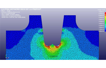
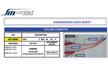
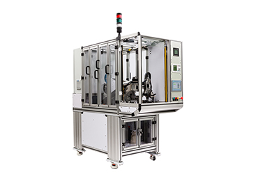
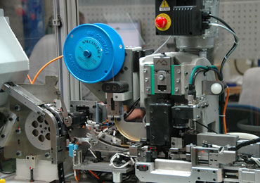
Customization and reliability of splice solution is further enhanced, since our R&D department defines optimal connection, tooling and splice band parameters in the beginning of the project.

Splice connections are widely used by automotive components suppliers of VW, BMW, PSA, Renault, etc.

Find out more about splice advantages and application below.
RELATED TOPICS SPLICE EQUIPMENT


  • 1. Components positioning
    1. Components positioning
    Components are located in splice crimping area of a
    machine in a proper order.
  • 2. Splice band cutting
    2. Splice band cutting
    Metal clip of a required length is cut from the reel-wound splice band and moved down to the components.
  • 3. Splicing the components
    3. Splicing the components
    U-shape splice is compressed tightly around the components’ ends
  • APPLICATION FIELDS
  • COMPONENTS TYPES
  • ALTERNATIVE ENERGY
    ALTERNATIVE ENERGY
    ALTERNATIVE ENERGY
  • ALTERNATIVE ENERGY
    ALTERNATIVE ENERGY
    ALTERNATIVE ENERGY
  • ALTERNATIVE ENERGY
    ALTERNATIVE ENERGY
    ALTERNATIVE ENERGY
  • ALTERNATIVE ENERGY
    ALTERNATIVE ENERGY
    ALTERNATIVE ENERGY
  • ALTERNATIVE ENERGY
    ALTERNATIVE ENERGY
    ALTERNATIVE ENERGY
  • ALTERNATIVE ENERGY
    ALTERNATIVE ENERGY
    ALTERNATIVE ENERGY
  • ALTERNATIVE ENERGY
    ALTERNATIVE ENERGY
    ALTERNATIVE ENERGY
  • ALTERNATIVE ENERGY
    ALTERNATIVE ENERGY
    ALTERNATIVE ENERGY
  • CORDS
    CORDS
    CORDS
  • DIODE & RESISTOR
    DIODE & RESISTOR
    DIODE & RESISTOR
  • FILAMENT
    FILAMENT
    FILAMENT
  • WIRE & CAPACITOR
    WIRE & CAPACITOR
    WIRE & CAPACITOR
  • WIRE & COIL
    WIRE & COIL
    WIRE & COIL
  • WIRE & DIODE
    WIRE & DIODE
    WIRE & DIODE
  • WIRE & LEADFRAME
    WIRE & LEADFRAME
    WIRE & LEADFRAME
  • WIRE & METALTAB
    WIRE & METALTAB
    WIRE & METALTAB
  • WIRE & PCB
    WIRE & PCB
    WIRE & PCB
  • WIRE & SENSOR
    WIRE & SENSOR
    WIRE & SENSOR
  • WIRE & RESISTOR
    WIRE & RESISTOR
    WIRE & RESISTOR
  • WIRE & WIRE
    WIRE & WIRE
    WIRE & WIRE
  • PCB & COAXIAL CONNECTOR
    PCB & COAXIAL CONNECTOR
    PCB & COAXIAL CONNECTOR
  • WIRE & PIN
    WIRE & PIN
    WIRE & PIN
  • WIRE & PLASTIC CONNECTOR
    WIRE & PLASTIC CONNECTOR
    WIRE & PLASTIC CONNECTOR
  • WIRE & PLUG ADAPTER
    WIRE & PLUG ADAPTER
    WIRE & PLUG ADAPTER
  • WIRE & THERMAL FUSE
    WIRE & THERMAL FUSE
    WIRE & THERMAL FUSE
WHY DO YOU NEED IT?
SPLICE ADVANTAGES
Unlike soldering, splice technology ensures reproducible quality of a connection possible to control during production process and after it.
  • Reproducible quality
    Reproducible quality

    Splicing as a mechanical process allows getting reproducible high quality. With the same tooling and splice band the quality of a product stays the same from cycle to cycle.

  • Adaptable to product
    Adaptable to product

    Tooling is designed individually for each product so that the splice fits perfectly the components and form reliable connection.

  • Gastight
    Gastight

    The deformation of the components and the splice during the splicing process guarantees gastight connection.

  • Low electrical resistance
    Low electrical resistance

    Connection and tooling engineering guarantees stable low electrical resistance preventing loose strands, misaligned connection and other defects.

  • Deformation and vibrations<br>resistance
    Deformation and vibrations
    resistance

    Splice crimping doesn’t involve heating unlike soldering, thus it keeps components out of burning or melting risks and guarantees good behavior under deformation and vibrations.

  • Compact
    Compact

    Splice allows to make compact and constant size connection with minimum dimensions such as 0.46*0.24 mm cross-section connection for an artificial cardiac pacemaker. Space saving feature is ideal for sensors, bulbs, heating elements, etc.

  • Universal
    Universal

    Splice connection can be performed with various types of components (PCBs, wires, coils, sensors, plastic connectors, filament, etc.), materials (fiber, Teflon, chrome, steel, etc.) and size.

  • Quality control
    Quality control

    Splice allows to make compact and constant size connection with minimum dimensions such as 0.46*0.24 mm cross-section connection for an artificial cardiac pacemaker. Space saving feature is ideal for sensors, bulbs, heating elements, etc.

  • Easy to go
    Easy to go

    Thanks to automation it’s possible to make up to 2000 splices per hour without any experience in splicing.

  • Cost-efficient
    Cost-efficient

    Splice spare parts are cheaper than ones for welding and soldering and it need to be changed rarely: each 300 000 – 3 000 000 assemblies depending on spares and components type.

HOW DO WE DO IT?
SPLICE CONNECTION EXPERTISE
1. SPLICE BAND DEFINITION
2. TOOLING DEFINITION
3. SPLICE CONNECTION SIMULATION
4. LABORATORY TESTS
5. EQUIPMENT MANUFACTURING
6. FPC SOLUTION
SPLICE BAND DEFINITION
1. SPLICE BAND DEFINITION
We define splice band features depending on type of application, component materials, working environment and temperature range.
What you get?
Splice band material (LA, LE, CN, CE, IN), type (standard serrated, M-type), thickness (0.2 – 0.53 mm), length (1.5, 2, 3, 4, 6, 7 mm), and height.
TOOLING DEFINITION
2. TOOLING DEFINITION
With a help of FEA software and database of former realized connections, we build computer model of tooling and simulate strains and stresses during splice crimping.
What you get?
Equipment type, clincher type (standard, CI-type or special) and size, punch tip shape (standard or double trumpet), special tool necessity definition.
SPLICE CONNECTION SIMULATION
3. SPLICE CONNECTION SIMULATION
With a help of FEA software we build components computer model of defined type and materials and simulate strains and stresses during splice crimping.
What you get?
Optimal connection parameters and its improvement options are specified to match industry norms and Customer’s demand (connection dimensions and optimal components positioning, compression rate, internal stress levels, contact resistance, and interconnection surface).
LABORATORY TESTS
4. LABORATORY TESTS
We make samples and perform laboratory study: pull-force, electrical resistance, and galvanic corrosion measurements, as well as thermal stress test and cross-view research.
What you get?
Report and datasheet with precise connection parameters matching splice/crimp norms and validated for different splice heights and compression levels according components tolerance (optimal connection cross-view shape, tooling requirements, target connection dimensions for machine adjustment, etc.).
EQUIPMENT MANUFACTURING
5. EQUIPMENT MANUFACTURING
Engineering department adapts automation level, speed, special options and quality control devices.
What you get?
Splice crimping equipment customized for Customer’s application, as well as for quality, automation, cost and production volume requirements.
FPC SOLUTION
6. FPC SOLUTION
– Control List with all optimal connection dimensions and tolerances. – Viso 6microsection measurement software. – Annual re-validation of a connection.
What you get?
Automated splice quality control and timely support from SM Contact engineering staff.
SPLICE EQUIPMENT
Check out splice equipment options! Each machine can be customized to particular components, environment, automation level, and production volumes.
  • SM CONTACT FRANCE
    Headquarters est. 1986
    +33 (0) 1 64 63 66 66
    Fax +33 (0) 1 64 63 67 22
    smcontact@smcontact.eu
    20-22 voie Gallo Romaine
    77860 Quincy-Voisins, France
  • SM CONTACT ASIA
    Asian subsidiary est.2008
    +86 20 3992 0957
    info@smcontact.cn
    #5-#8, building A7,Huachuang Industrial
    Park,9 Huateng RD, Shiji Town,
    Panyu District,Guangzhou,China
  • SM CONTACT ENGINEERING
    Russian & CIS subsidiary est. 2011
    +7 (812) 980 97 93
    info@smcontact.ru
    21 lit. A Basseynaya Street
    196191 Saint Petersburg, Russia
  • SM CONTACT GmbH
    German subsidiary est. 2015
    +49 89 693 30812
    sales_de@smcontact.eu
    Alte Landstrasse 25
    D-85521 Ottobrunn, Germany
  • SM CONTACT SPAIN
    Spanish subsidiary est. 2017
    +34 645 22 62 37
    smcontact@smcontact.eu
    Carrer de Vilafranca, 7
    08024 Barcelona, Spain
  • SM CONTACT TECH
    Baltic subsidiary est. 2018
    +372 56 829 870
    orders_smct@smcontact.eu
    Kadastiku 57A
    21004 Narva, Estonia
  • Guangzhou Geulu Equipments for Electronic Products Co,Ltd
  • #5-#8, building A7 Huachuang Industrial Park , 9 Huateng RD, Shiji Town, Panyu Dist, Guangzhou , China
  • +86- 20-3992 0957

    info@smcontact.cn

    m.chinajiangmao.com

? SM Contact 2019 粵ICP備20018780號
PARTNER ACCESS
I have read the Privacy and Cookies policy and consent to the collection, processing and use of my personal data.
PARTNER REGISTER
I have read the Privacy and Cookies policy and consent to the collection, processing and use of my personal data.
*Required fields
REGISTER
主站蜘蛛池模板: 久久久成人精品av四区| 久久中文字幕无码中文字幕有码| 18禁美女裸体无遮挡免费观看国产| 久久只精品99品免费久23| 色悠久久久久综合网国产| 激情图片激情小说| av成人无码无在线观看| 久久久无码精品亚洲日韩蜜臀浪潮| 国产无遮挡裸体免费视频 | 无码国产精品一区二区免费模式| 久久人人做人人妻人人玩精品hd| 成人欧美日韩一区二区三区| 乱成熟女人在线视频| 国产精品无码a∨精品影院app| 天堂网www在线资源| 欧美人妻体内射射| av成人无码无在线观看| 在国产线视频a在线视频| 人人澡人人曰人人摸看| 在线亚洲精品国产成人av剧情| 兔费看少妇性l交大片免费| 亚洲中久无码永久在线观看软件| 无码人妻丰满熟妇区10p| 精品精品国产高清a毛片| 四虎国产精品永久地址49| 欧美黑人性暴力猛交喷水| 日本高清一二三不卡区| 欧美性群另类交| 未满十八18勿进黄网站| 国产精品久久久久蜜芽| 中国少妇xxxx做受| 搡老熟女老女人一区二区| 精品久久国产字幕高潮| 天天天狠天天碰天天爱| 亚洲欧美另类激情综合区蜜芽| 成在人线av无码免费看| 九九热爱视频精品视频| 亚洲精品乱码久久久久红杏| av片在线观看| 狠狠久久精品中文字幕无码| 九九热久久只有精品2|